technical information bulletin #2 |
|
technical information bulletin #2 |
|
Home Tech. Menu Decoders Bulletin #1 Spare Parts Eras Schematics
2.1 The possibilities for installing
sound effects electronics in older 1 Gauge models
The recognized excellent sound image that the new 1 Gauge sound effects electronics
produce in the class 218 and V200 diesel locomotives and in the T93 steam locomotive have awakened in many consumers
the desire to install this acoustic state-of-the-art technology into older 1 Gauge models.
The following statements can be made about this from the current perspective on the
subject:
• With the exception of the class 218 (5571, 85571 and
55711) that comes from the factory ready for installation of the 56560 sound effects
electronic circuit, considerable modifications are required on all other models. In some
cases synchronizer generators and new hardware for mounting the electronic circuits must
be installed, and on many models a new digital circuit board is necessary.
• For the above reasons retrofit kits for end consumers will not be offered.
• For some models we see the possibility that authorized repair stations could do the
conversion of older models. The necessary preparatory work for this means that we cannot
offer this service before the year 2000. We will inform you as soon as possible which
models can be converted and at what cost.
• In any event we strongly recommend against consumers or dealers doing their own
experiments with the sound effects circuit and decoder from the 55910. In terms of its
dimensions the sound effects circuit from 55241 (DRG class 78) is a better candidate for
use in converting other locomotives.
2.2. Displaying and storing
locomotives
Locomotives that are on display in cases or that are stored for long periods of time
should be run at least once a year and should be checked out to make sure that they work
properly. Oiling a locomotive before storing it. is -detrimental, since the danger of the
oil hardening in the different axle bearings increases. Although the Marklin oil (item no.
7149) is made to particular specifications, this product may harden over long periods of
storage time!
2.3 Pickup shoe changeover on the ICE
2
One of the special technical features of the different ICE trains has always been the
built-in power changeover between the pickup shoes and pantographs. This technology
guarantees that the train always stops at a signal with the forward part of the train,
regardless of the direction of travel.
This is also the case with the ICE 2
(33712/37712) if it is receiving its power through the track. This even holds true, when a
"dummy" train (non-powered unit, item no. 40712) is coupled to it.
Since as a single train the ICE 2 has only one pantograph that is located on the powered
unit, there can be no power changeover on this model when it is powered through the
catenary. If the cab control car is at the front of the train, the entire train down to
the powered unit will be pushed beyond the dead signal block.
Even when the second "dummy" train is used, the installation of a power
changeover between the pantographs does not make any sense. As with the prototype the two
trains can also be combined with each other in any one of several ways, so that, for
example, one or both power units can be located in the middle of the train. For that
reason a power changeover is also not possible in these situations, this technology was
not installed in the ICE 2 right from the start.
Mind you, this only holds true when the train is powered through the catenary. If the
train is being powered through the track, power changeover between the pickup shoes is
naturally built in!
Three pieces of information related to this:
• A switch is located on the underside of each power car and cab control car so that
the power changeover between the pickup shoes will function with a single train or a
double train. This switch is identified with the letters "E" and "D".
Some customers have mistakenly connected this "D" with Digital. The letters
actually mean that the pickup shoes in question under the car is either electrically
connected ("E" position) or is not connected and therefore has no function as a
"D"ummy. Both of the motor or cab control cars at the ends of the train must
always be operated in the "E" position, while the pickup shoes on the two motor
or cab control cars in the middle of the train are turned off ("D" position).
• Operation of the ICE 2 by means of catenary has still another handicap in addition
to the missing power changeover between the pickup shoes- Since the reliability of the
power pickup through a single pantograph is much worse than that of a center rail pickup
shoe, in digital operation there is the possibility that operating data may be received
garbled and thereby disrupted by the locomotive decoder. The faster a train or powered
unit is run and the greater the tolerances in the setup of the catenary, the more likely
this problem is to occur. For that reason we are hesitant to recommend powering the train
through the catenary when using digital.
• Because of the power changeover between the pickup shoes, the motorized parts of
the different ICE trains and the DB Cargo Sprinter cannot be operated by themselves!
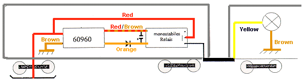
2.4. Installing the 60960
in cars to control lighting
In the brochure "Installation information for HO decoders" (no. 603712) mention
is made on page 5, left column, 2nd paragraph, of a single step relay. We have received
many inquiries about specific information about this relay and whether this part is
available from Marklin as a spare part.
The single step relay should be designed for a switching voltage of 12 volts and a contact
load limit with a minimum of 1 amp, if this relay is also to be activated in conventional
operation (on function fl). With pure digital operation it is recommended that you use an
18 or 24 volt version with at least the same contact load limit. Designs with a minimal
current draw on the exciter side are preferred. A center zero relay is required at the
output (An input contact is connected to one of two output contacts depending on the
switching status of the relay). This relay is also available in mini versions for mounting
on a small circuit board, which is easier to install in HO cars. This relay can be
purchased at reasonable prices in any electronic supply outlet. This type of relay is not
available at present as a Marklin spare part.
The diagram below shows the basic installation of such a relay. The diode shown is a type
1 N 4148, and the electrolytic condenser should have a capacity of 10 micro Farad. This
supplemental circuit keeps the relay from "chattering" (constant on and off
action of the relay due to a pulsating direct current).
In this example the adjacent car is supposed to be provided with controlled lighting
through the current-conducting coupler. The other control outputs on the decoder can
naturally also be used for other switching purposes. This circuit was left out of the
drawing in the interests of clarity.
Home Tech. Menu Decoders Bulletin #1 Spare Parts Eras Schematics